Thursday 20 October 2011

New inspiration weekly: LED lamps

 In this series I will try to present some of the very good ideas I have found in the net. Every post will be inspired by one simple idea. This weeks main topic is: LED lamps. So everything connected to this topic -- that put a smile on my face -- will be presented below. Enjoy!

Image 1. DIY New Year's Eve LED ball.
  1. The most beautiful of all my findings (Image 1) was this DIY New Year's Eve LED ball. This combines a rather normal LED multicoloured lamp with a simply-brilliant look. So when I will think about my mood-room in a near future, this will be my mood-lamp.


  2. The second best (Movie 1) is not really a proper "lamp", but still it can be used as a "lamp" that lights the room while You are watching a movie. Yes, yes it is called ambilight. But the presented solution of ambilight is more interesting, because one can build it for himself... :D. In fact, at the moment I am considering to buy this stuff and simply make it.


  3. Image 2. Slamp
  4. The next shining lamp (Image 2) does not seem to use LEDs inside, but I can imagine, that it would look also brilliant if not even better.

  5. Last but not least, a simple lightning system that is meant to be self assembled. The whole idea is to create a 3Dimensional shape, for example a cube. The Cube is a rather simple example. Much more complex can contain about 120 elements. A quick thought makes me wonder, how a combination of multicoloured LEDs from the Image 1 would look in this lightning system.

Friday 14 October 2011

Stepper motors 2

At the beginning of this post it would be necesary to mention the basics of MOSFET transistors. Although the WIKI site contains all important info, for some of the amatours (like me in some way) it is to much. I will try to provide the most important information about this transistor using one example.

The schema presented below (Image 1) shows a circuit with one IRF540Z transistor, two resistors and a red LED (btw, a very good site about LEDs).

Image 1. Circuit presenting the work of the MOSFET. Created with TinyCad.


Please note that in this image the model of the transistor IRF540Z differs from the one presented in the catalogue. This occured because TinyCad does not have all available transistors in its database. Still the circuit remains correct.

The inputs in this circuit show 5V and GND which is usual, but the PIN13 refers to the 13-th PIN on the arduino board. Then, loading the Simple Blink example You will blink with the LED. One could ask why to buy a transistor and make all this simply to blink, but there is a very good reason for it. The gate of this transistor can be turned OFF and ON by a Voltage VGS(th), and this is below 2V for OFF and above 4V for ON. But this is not the benefit here. The most valuable thing this transistor does is to allow a hudge current to flow through it. Using the gate You can manipulate with high voltage, allowing it to flow, or not. The max parameters of this transistor are shown in the mentioned catalogue, and these are in fact very good: VDSS = 100V and ID = 36A.

In this simple example we are working with a simple LED diode. But the previous article shows the main target, the KT42JM06 hybrid stepper.

So having worked with a transistor now, we can get to the motor driver.
I have slightly modified the schema placing some resistors and input pin numbers. The image 2 shows the almost final driver circuit.
Image 2. Proposed driver schema. Created with TinyCad.
 This seems to be a little more complicated than the original one, and the transistors again differ to the used IRF540Z, but still it is not a problem to understand the whole concept.

Combining it all together with a software (Fritzing is a very good one) and a virtual breadboard gives something like the image 3. Please note, that the Stepper Motor there has got one winding left, this has been made on purpose, because the KT42JM06 has 4 outputs, and one of them is a fake one. As You will soon see the one left is not needed to allow the motor to work.
Image 3. Circuit plan, created using Fritzing.
I have not mentioned it earlier, but my assumptions at the beginnig where strictly connected to the Exciting Sequence I have presented earlier (image 1). I thought the following:
  1. in every little step, one winding of the motor has to be isolated
  2. in every little step, one winding conducts the current in one direction, and the secont in a different one.
So considering these points our circuit has to do the following, (talking about the first step for the motor):
  1. the winding W should be isolated and we will achieve that when the transistors T1 and T2 will NOT conduct the current, so the state on PIN2 and PIN3 will both be LOW,
  2. the winding U should have the +, so we conduct the current through the T3 turning the T4 OFF, on the other hand the last winding V should have -, so we will conduct the current through it in a different direction: via T6, having turned the T5 OFF.

So having all this it is time to present the effects of the whole work.

Additional Note:

In this video I have used a 12V, 1.5A power suply, which was in fact not enough (though it still worked :)). You may encounter circuits in which the power consumption is higher, and the transistors operate with that high power all the time. So in order not to destroy them one has to provide a cooling system. Radiators are a good idea. To check if a transistor needs a radiator one has simply to calculate the power that will be lost on the transistor: P=R*I*I => 26.5*10^-3 * 1.5 * 1.5 = 0.059625W so this is a lot less than 1W. The transistor used here can survive working with about 1W of power loss without getting destroyed.

Sunday 9 October 2011

Stepper motors 1

A motivation for this (not only) post was a homemade cnc drill, to which sadly I cannot find a link now. But googling for a while will show You how much of this is really out there. So I immediately wanted to build it for myself.

The first problems where the stepper motors. I read something about them and knew, that there are really 3 types of motors on the market: bipolars, unipolars and hybrids. After some days I have managed to buy some used steppers on our polish eBay (allegro). The type I bought was a KT42JM06-006. This according to the transcription of the code (this pdf, on page 29) was a 3 phase hybrid stepper motor with 0.6 degree per step, so a very precise one. On the yellow sticker there was some additional information like the voltage: DC24V, 1.5A/2 Phase.

So I had the motors, but what about the driver? I had no idea how to start with it. The dedicated drivers for this motor would cost a fortune, and I wanted to: a) create everything from 'scratch' b) spend a fortune on something else. That was a motivator to start reading the motors documentation. I found there the exciting sequence.
Image 1. The Windings and the Exciting sequence of the KT42JM06 motor.
OK, that will be a tricky one, because that is a hybrid, not a bipolar, nor a unipolar, so the usual drivers will not be good for it. After a while of thinking and researching the google I found 2 Ideas: 1 and 
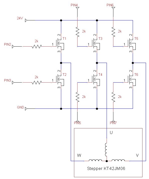
2, from which I have mended myself (inspired by the second Idea :)) a circuit which is presented in the Image 2.
Image 2. The proposed circuit. Created using TinyCad.
I am not very experienced in any type of transistors (mainly because it is not very necessary for a software developer in everyday work). So the facts stop here, but the dream carries on. I think there are tons of different transistors on the market, and few of them would be suitable for this task. My expectations considering the transistors in this circuit are as follows:
  • The gate of each transistor is controlled by a 0-5 voltage, which causes the transistor to conduct the current or turn itself off respectively.
  • The current conducted by the transistor will be enough to steer the stepper.
  • The transistors will not be destroyed during the work.
  • .... will they get hot? ...
 I have chosen the FET transistors, but as I said, I don't have much experience in such transistor containing circuits (I played a lot with the logical gates and so one, but not the transistors only). So when You have any suggestions to this stepper motor driver I am all ears.

Saturday 8 October 2011

Startup

I am a software engineer, working at a Capgemini office in Wroclaw-Poland. Some time ago I graduated from my Software Engineering studies at the University of Technology in Wroclaw. So I am a Computer Programmer working with the tools I like to deliver stuff I like. But there are 'things' I like more than just programming, of course apart from loving my Wife of course. These are more physical than lines of code in any of the existing programming languages. This is the hardware I like o play around with.

Everything started as a innocent Lego love when I was so small I cannot really recall. This has been very innocent until some time ago, when I Stumbled across the makezine blog. This was like a kind of bookshelf full of good ideas, ideas I liked and wanted to realise myself sometime in the future. But the makezine was not first in my RSS reader, its was the second source of ideas, right after notcot. But it was better for me, more in to the process of making than just the finished product. After a short research in the archives of the makezine blog I have been captivated by the arduino and the idea of Open Source Hardware. So after some weeks my brothers bought me an arduino Uno for my birthday. I loved it almost instantly (some of my rather nooby achievements are available here: UTube, for the code behind it, please give me a comment).

As You have probably thought, this blog will be about hardware in fusion with software. I will try to do my best in the questions I will ask and the answers I will give. This will be my 'diary' for some of my future projects, and a small bookshelf of ideas so You can also profit from it.

Please don't hesitate to ask me questions and get involve into my projects. I hope this will be inspiring for You too.